Abstract
The installation of mechanical joint pipe and fittings represents a foundational practice in modern fluid and gas conveyance systems, demanding a synthesis of procedural rigor and material understanding. This document examines the process, articulating the sequence of actions required to achieve a durable, leak-free connection. It begins with an exploration of preparatory stages, including material inspection, pipe end preparation, and the selection of appropriate tools. The discourse then proceeds to the core mechanics of assembly, focusing on the correct placement of the gasket, the principles of lubrication, and the methodical tightening of bolts to achieve specified torque values. The analysis extends to post-installation procedures such as visual inspection and hydrostatic testing, which serve to validate the integrity of the joint. By deconstructing the installation into its constituent elements, from the chemical interaction of lubricant and gasket to the physical forces governed by torque, this guide provides a comprehensive framework for practitioners. The objective is to foster an approach grounded in precision and informed by the engineering principles that ensure the long-term stability and safety of pipeline infrastructure.
Key Takeaways
- Thoroughly clean and inspect all pipe ends and fitting sockets before assembly.
- Apply an approved, non-toxic lubricant evenly to the gasket and pipe end.
- Hand-tighten bolts initially, then use a torque wrench in a star pattern.
- Properly installing mechanical joint pipe and fittings ensures a long-lasting, leak-proof seal.
- Always verify the correct torque specifications for the bolt size and material.
- Conduct a visual inspection and pressure test after assembly to confirm integrity.
- Ensure pipes are correctly aligned to prevent stress and potential gasket damage.
Table of Contents
- Understanding the Anatomy of a Mechanical Joint
- Preparation: The Bedrock of a Successful Installation
- Step 1: Meticulous Pipe and Fitting Preparation
- Step 2: The Critical Role of Gasket and Lubrication
- Step 3: The Mechanical Dance of Assembly and Alignment
- Step 4: The Science of Torque and Bolt Tightening
- Step 5: Verification Through Inspection and Testing
- Step 6: Navigating and Rectifying Common Installation Faults
- Step 7: Ensuring Longevity Through Maintenance and Care
- Frequently Asked Questions (FAQ)
- A Final Reflection on Craft and Connection
- References
Understanding the Anatomy of a Mechanical Joint
Before one can embark on the practical task of installation, a deeper appreciation for the object of our attention is necessary. The mechanical joint is not merely a collection of parts; it is a sophisticated system designed to reconcile the need for a robust, pressure-tight seal with the practical realities of field installation. It represents a significant evolution from older, more labor-intensive methods like lead-caulked bell-and-spigot joints or rigid welded connections. At its core, the mechanical joint is an expression of ingenuity, a testament to the human capacity to solve complex physical problems with elegant, functional design.

The Philosophical Underpinnings of a Secure Joint
To connect two pipes is to create a conduit, a continuous path where one was previously absent. This act of joining carries with it a profound responsibility. The integrity of that connection determines the reliability of the entire system, whether it conveys life-sustaining water to a community or critical fluids within an industrial process. A failure is not just a leak; it is a breach of continuity, a disruption of function, and a potential hazard. The mechanical joint, in its design, embodies a philosophy of controlled compression. Unlike a rigid weld that creates a monolithic structure, the mechanical joint employs a dynamic equilibrium of forces. The bolts, gland, and gasket work in concert to create a seal that is both strong and flexible, capable of accommodating the subtle shifts and stresses that any pipeline will experience over its lifetime. This inherent flexibility speaks to a more nuanced understanding of permanence—not as absolute rigidity, but as resilient adaptability.
From Antiquity to Modernity: A Brief History of Pipe Joining
The challenge of joining pipes is as old as civilization’s first attempts to manage water. Ancient Roman aqueducts used rudimentary stone and mortar techniques. For centuries, the standard for iron pipe was the bell-and-spigot joint, painstakingly sealed with packed oakum and molten lead—a process demanding immense skill and fraught with hazards. The 20th century brought welding and flanging, which offered greater strength but introduced their own complexities, requiring specialized equipment, highly skilled labor, and controlled environments.
The mechanical joint emerged in the mid-20th century as a direct response to these challenges. Its invention was driven by a desire for a joining method that was fast, reliable, simple, and safe. The design, standardized by bodies like the American Water Works Association (AWWA), allowed for rapid assembly in a variety of field conditions, often in a wet trench, without the need for heat or electricity. It democratized the process, reducing reliance on a small pool of specialized artisans and enabling more efficient construction of the vast water and wastewater networks that underpin modern society. This transition reflects a broader trend in engineering toward modularity, standardization, and a focus on the entire lifecycle of a system, from installation to maintenance.
Deconstructing the Mechanical Joint: Components and Principles
To understand how to install mechanical joint pipe and fittings, one must first become intimately familiar with its constituent parts. Each component has a specific function, and their interplay is what creates the seal.
| Component | Material (Typical) | Function |
|---|---|---|
| Integral Bell | Ductile Iron | The female end of the pipe or fitting, featuring an internal socket to house the gasket and a flange with bolt holes. |
| Plain End (Spigot) | Ductile Iron | The male end of the pipe that is inserted into the bell. |
| Gasket | SBR, EPDM, or NBR Rubber | The primary sealing element. It is compressed within the socket to create a pressure-tight barrier against leakage. |
| Gland | Ductile Iron | A ring that fits over the plain end of the pipe. It compresses the gasket into the socket as the bolts are tightened. |
| T-Head Bolts & Nuts | High-Strength, Low-Alloy Steel | The fasteners that pass through the gland and the bell’s flange. When tightened, they provide the clamping force. |
The principle is one of mechanical compression. The plain end of a pipe is inserted into the bell of another pipe or fitting. A rubber gasket is stretched over the plain end and seated within the bell’s socket. The gland is then brought up and bolted to the bell. As the bolts are tightened, the gland pushes against the gasket, compressing it radially against the pipe’s plain end and axially into the bell’s socket. This uniform compression creates a formidable seal, capable of withstanding significant internal pressure and external loads. The T-head design of the bolts is a thoughtful detail, preventing the bolt from turning as the nut is tightened, simplifying assembly in the often-confined space of a trench.
Preparation: The Bedrock of a Successful Installation
The quality of any constructed work is determined long before the final piece is set in place. The preparatory phase of installing mechanical joints is not a preliminary chore but the very foundation upon which the integrity of the entire pipeline rests. A rushed or careless approach at this stage will inevitably manifest as problems later, whether as frustrating delays, costly leaks, or catastrophic failures. A methodical and conscientious preparation is an investment in certainty.
Site and Material Inspection: The Foundation of Safety
Before any pipe is moved or any tool is lifted, the installer must first engage with the environment and the materials. This is an act of observation and assessment.
- Trench and Site Evaluation: Examine the trench itself. Is it stable and free of loose rocks or debris that could fall? Is there adequate space to work safely around the pipe? Is the trench bottom graded correctly and free of standing water? The environment dictates the terms of the work, and ignoring its conditions is a primary source of both accidents and poor-quality installation.
- Material Verification: Unload and handle pipes and fittings with care, using appropriate slings and equipment to avoid damaging the pipe walls or factory-applied coatings. Once unloaded, conduct a thorough inspection. Check each piece against the project’s bill of materials. Is it the correct size, class, and type? Look for any signs of damage that may have occurred during shipping. A hairline crack in a fitting’s bell or a deep gouge on a pipe’s plain end might seem minor, but under pressure, these become points of failure. A comprehensive assortment of high-quality Mechanical Joint Fittings is paramount for system compatibility and performance.
- Component Check: Open the boxes containing the gaskets, glands, and bolts. Confirm that they are the correct size for the pipe and that you have a sufficient quantity. Inspect the bolts and nuts to ensure the threads are clean and undamaged. Examine the gaskets for any cuts, tears, or signs of aging or improper storage (such as ozone cracking). The smallest component is often the most critical; the entire joint’s integrity depends on a single rubber ring and a handful of bolts.
Understanding Your Materials: Pipe and Fitting Specifications
Not all pipes and fittings are created equal. They are manufactured to different standards and from various materials to suit a wide range of applications, from potable water to corrosive industrial chemicals. Understanding these distinctions is fundamental. The most common material for water distribution systems is ductile iron, prized for its high tensile strength, ductility, and impact resistance (Norton, 2021). Other materials, such as PVC or specialized alloys, may be used in other contexts. The installer must be aware of the specific properties and handling requirements of the materials at hand. Consulting a detailed product resource, like a galvanized pipe fittings catalog for specific applications, can provide clarity on material specifications and corrosion resistance properties.
| Characteristic | Ductile Iron Pipe (DIP) | PVC Pipe | Galvanized Steel Pipe |
|---|---|---|---|
| Joining Method | Mechanical Joint, Push-On, Flanged | Solvent Cement, Gasketed Bell | Threaded, Grooved, Flanged |
| Strength | Very High Tensile & Compressive | Moderate | High |
| Corrosion | Good (often lined/coated) | Excellent (inert) | Poor (zinc coating is sacrificial) |
| Flexibility | Moderate (ductile) | High (flexible) | Low (rigid) |
| Weight | Heavy | Lightweight | Heavy |
| Common Uses | Water/Wastewater Mains | Irrigation, Drains, Water Service | Fire Sprinklers, Gas, Industrial |
Essential Tools and Equipment: Assembling Your Arsenal
Attempting to install mechanical joints without the proper tools is an exercise in futility and a recipe for failure. Having the correct equipment ready and in good working order is a mark of professionalism.
- Cleaning Supplies: Wire brushes (both manual and for power drills), clean rags, and solvent (if permitted by the manufacturer) are necessary for preparing pipe ends.
- Lubrication Tools: A bucket for the lubricant and a clean glove, brush, or swab for application.
- Assembly and Lifting Equipment: Depending on the pipe size, this can range from simple wood blocks for support to chain hoists, slings, and heavy machinery for lifting and aligning large-diameter pipes.
- Torque Wrench: This is the most important tool for the final assembly. It must be a calibrated, functioning torque wrench of the appropriate size and range for the bolts being used. Relying on “feel” or standard wrenches is unacceptable; it guarantees inconsistent and incorrect bolt loading.
- Standard Wrenches: Socket or box-end wrenches that fit the nuts are needed for the initial tightening stages.
- Safety Gear: Personal Protective Equipment (PPE) is non-negotiable. This includes hard hats, steel-toed boots, safety glasses, and gloves.
Safety Protocols: A Non-Negotiable Prerequisite
The installation of pipelines, particularly in trenches, carries inherent risks. A culture of safety must pervade every action. This involves more than just wearing a hard hat; it demands a constant state of situational awareness. Personnel must be trained in trench safety, including procedures for entry, exit, and emergency response in the event of a cave-in. They must understand the weight of the materials they are handling and use correct lifting techniques to prevent injury. When pressure testing the line, the area must be cleared, and all personnel must understand the potential energy stored in the pressurized system. Safety is not a separate step in the process; it is the context in which the entire process must occur.
Step 1: Meticulous Pipe and Fitting Preparation
The journey toward a perfect seal begins with the surfaces that will form it. The interface between the pipe, the gasket, and the fitting’s socket is where the battle against leaks is won or lost. Any foreign material—dirt, sand, ice, or grease—can create a pathway for water to escape under pressure. Therefore, the preparation of these surfaces is not a janitorial task but a technical procedure of the highest importance.
The Imperative of a Clean Surface
Imagine trying to create an airtight seal with a piece of tape on a dusty surface. It simply will not work. The adhesive needs to make direct contact with the surface itself. The same principle applies to a mechanical joint gasket. The rubber must be in direct, intimate contact with the smooth, clean surfaces of the pipe’s plain end and the fitting’s socket.
The process is straightforward but must be done with care. Using a wire brush, thoroughly clean the inside of the fitting’s bell, paying special attention to the gasket seat and the interior surface where the seal will be made. Remove all traces of dirt, mud, rust scale, or the temporary coating often applied for shipping. Follow this by cleaning the plain end of the pipe that will be inserted. Clean a larger area than you think is necessary, extending back from the end of the pipe at least a foot or two. Once the surfaces are brushed, wipe them down with a clean, dry rag to remove any remaining dust or debris. In cold weather, ensure that there is no frost or ice on the mating surfaces, as this will melt during testing and create a leak.
Inspecting Pipe Ends for Defects
As you clean, you must also inspect. Run your hand and your eye over the cleaned surfaces. Feel for any burrs, gouges, or flat spots. Look for any delamination of the pipe material or cracks, especially around the beveled edge of the plain end. A significant defect on the pipe’s sealing surface can compromise the gasket’s ability to conform and create a complete seal. Similarly, inspect the inner surface of the bell and the gasket recess. Any casting flaw or damage at these locations can be a source of failure. If a significant defect is found, the pipe or fitting should be set aside and not used. The temptation to “make it work” must be resisted, as it gambles with the integrity of the entire system.
Creating a Smooth Bevel
Most ductile iron pipe is delivered from the factory with a beveled or chamfered plain end. This bevel is not an aesthetic choice; it is a functional necessity. It serves two purposes. First, it allows the pipe to be inserted into the bell more easily. Second, and more importantly, it allows the pipe to slide past the rubber gasket without pushing it out of its seat or damaging it. When a pipe must be cut in the field, the new end will be sharp and square. It is absolutely essential to recreate the factory bevel on this field-cut end. Using a portable grinder or a coarse file, grind a gentle taper around the outside edge of the pipe. The goal is to replicate the smooth, rounded transition of a factory end. A sharp edge will act like a knife, potentially cutting the gasket or bunching it up in the socket, creating a guaranteed leak. This small, often overlooked step is a defining characteristic of professional installation.
Step 2: The Critical Role of Gasket and Lubrication
If the bolts and gland are the muscle of the mechanical joint, the gasket is its heart, and the lubricant is the lifeblood that allows it to function correctly. This stage of the process involves a delicate interplay of materials science and careful application. An incorrect lubricant, or a correct lubricant improperly applied, can be as detrimental as a cracked fitting or an under-torqued bolt.
The Role of the Gasket: More Than Just a Rubber Ring
The gasket is a marvel of polymer engineering. It is designed to be soft and flexible enough to conform to the microscopic imperfections of the pipe and fitting surfaces, yet strong and resilient enough to withstand high pressures and maintain its sealing force for decades. Gaskets are made from different rubber compounds depending on the intended service.
- SBR (Styrene-Butadiene Rubber): The standard for water and wastewater applications. It has excellent physical properties and is cost-effective.
- EPDM (Ethylene Propylene Diene Monomer): Often used for higher temperatures or where superior resistance to ozone and weathering is required.
- NBR (Nitrile Butadiene Rubber) or Nitrile: Used for pipelines carrying petroleum products, oils, or certain chemicals, as it has excellent resistance to these substances which would degrade SBR or EPDM.
Using the wrong gasket can lead to rapid failure. A standard SBR gasket in a gasoline line will swell, soften, and disintegrate. Therefore, it is essential to verify that the gasket material is appropriate for the fluid being conveyed. The gasket should be placed over the plain end of the pipe, with the thicker, rounded edge (the bulb) facing the end of the pipe. Slide it along the pipe until it is a few inches from the end, ready to be inserted into the bell.
Selecting the Correct Lubricant: A Chemical Consideration
Lubrication is not optional. It is a required step in the standard installation procedure (AWWA, 2017). The lubricant performs two functions. First, it reduces the friction between the rubber gasket and the iron pipe, allowing the plain end to slide into the bell and past the gasket without displacing or damaging it. Second, it helps the gasket seat properly, allowing it to slide and adjust into its final, compressed position.
The choice of lubricant is critical. Only lubricants that are specifically approved for use with potable water pipe and the specific gasket material should be used. These lubricants are soap-based, non-toxic, and will not impart any taste or odor to the water. They are also designed to be chemically compatible with the rubber gasket, ensuring they will not cause it to degrade over time.
| Lubricant Type | Common Base | Advantages | Disadvantages |
|---|---|---|---|
| Soap-Based | Vegetable Soap | Non-toxic, water soluble, approved for potable water. | Can wash away in very wet conditions. May support mold growth if not used promptly. |
| Silicone-Based | Silicone Grease | Excellent lubrication, water repellent, wide temperature range. | More expensive. Can be difficult to clean up. May not be approved for all potable water systems. |
| Petroleum-Based | Grease/Oil | N/A | NEVER USE. It is toxic and will severely damage rubber gaskets. |
| Anti-Seize | Metallic/Graphite | N/A | NEVER USE. Designed for threaded fasteners, not for gasket lubrication. |
Under no circumstances should petroleum-based grease, oil, or any other unapproved substance be used. These materials can have a devastating effect on the rubber gasket, causing it to swell, soften, or become brittle, leading to premature failure of the joint.
The Art of Lubrication: Applying the Right Amount in the Right Place
With the correct lubricant selected, the application must be done thoughtfully. The goal is to apply a thin, even film to the necessary surfaces. Using a clean glove or a small brush, apply lubricant to two areas:
- The inside surface of the gasket: Apply a thin layer to the inner surface of the gasket that will be in contact with the pipe’s plain end.
- The outside of the pipe’s plain end: Apply a generous layer to the entire beveled end and the first few inches of the pipe’s cylindrical surface.
There is no need to apply lubricant to the inside of the fitting’s bell. Doing so can trap excess lubricant in the socket, potentially interfering with the gasket’s proper seating. Do not be stingy with the lubricant on the pipe end, but do not simply slop it on. A methodical, even coating is the objective. This ensures that every point of contact between the pipe and gasket experiences reduced friction during assembly.
Step 3: The Mechanical Dance of Assembly and Alignment
This is the moment of union, where separate components are brought together to form a single, functional joint. It is a physical process that requires both strength and finesse. Proper alignment is the guiding principle of this stage. A misaligned joint is a stressed joint, and a stressed joint is destined to fail.
Achieving Proper Pipe Alignment: The Geometry of a Good Seal
Before attempting to insert the pipe, it must be brought into near-perfect alignment with the fitting’s bell. The centerline of the pipe should be a direct continuation of the centerline of the fitting. The pipe should be supported by blocks, sandbags, or other means so that it is not hanging or being forced into position. Forcing a pipe into alignment by pulling it sideways with a bar or a backhoe places enormous stress on the already-assembled parts of the pipeline and makes it almost impossible to achieve a good seal at the new joint.
Think of it as threading a very large, very heavy needle. You do not force the thread through the eye; you guide it. Similarly, the pipe must be guided into the bell. If the alignment is correct, the insertion will require surprisingly little force. If significant force is required, it is a sign that something is wrong. Stop, pull the pipe back, and re-check the alignment.
Inserting the Spigot into the Bell
With the pipe aligned and supported, the insertion can begin. Push the pipe forward so that the plain end enters the bell. As the beveled end makes contact with the lubricated gasket, you should feel a slight increase in resistance. A firm, steady push should then cause the pipe to slide through the gasket. The pipe should be inserted until it makes contact with the back of the bell’s socket. There is often a painted stripe on the plain end of the pipe to serve as a visual guide for the correct insertion depth. Pushing the pipe in too far or not far enough can affect the joint’s ability to accommodate expansion, contraction, and deflection.
Once the pipe is inserted, slide the gasket forward along the pipe until it is flush against the face of the bell. Then, using your fingers or a small, blunt tool, push the gasket into the bell’s socket, ensuring it is seated evenly all the way around its circumference. You should not see any part of the gasket twisted or pinched.
Positioning the Gland and Bolts
With the pipe and gasket in place, the gland can be installed. Slide the gland forward along the pipe until it is against the gasket. The gland has a convex lip that is designed to fit into the concave face of the gasket. Ensure it is oriented correctly. The gland should slide up evenly against the gasket. If it is cocked to one side, it means the pipe is not properly aligned within the bell.
Now, insert the T-head bolts. Place them through the bolt holes on the bell’s flange from the back, so the T-head is on the inside of the flange and the threaded end is pointing forward. The T-head will fit into a recess that prevents it from turning. Rotate the gland so its bolt holes line up with the bolts, and slide the gland over the bolts. Finally, place a nut on each bolt and tighten it by hand until it is snug. At this point, all the components are in place, but no sealing force has been applied. The joint is assembled but not yet complete.
Step 4: The Science of Torque and Bolt Tightening
This is arguably the most technically demanding and misunderstood part of the entire process. The simple act of turning a nut on a bolt is transformed into a precise engineering procedure. It is here that the potential energy of the installer’s effort is converted into the kinetic energy of compression that creates the seal. To do this correctly is to understand the physics of torque.
The Physics of Torque: Clamping Force Explained
Torque is a measure of rotational force. When you apply torque to a nut with a wrench, you are stretching the bolt like a very stiff spring. This stretching creates tension in the bolt, which in turn generates a clamping force that pulls the gland and the bell together. It is this clamping force that compresses the gasket.
- Too little torque: The bolt is not stretched enough. The clamping force is insufficient to fully compress the gasket. A leak is almost certain, especially as pressure increases.
- Too much torque: The bolt can be stretched beyond its elastic limit, a point from which it cannot recover. It may be permanently weakened or even break. Excessive clamping force can also damage the gland or the bell’s flange, or it can over-compress the gasket, squeezing it out of the joint or damaging its internal structure.
The goal is to apply the precise amount of torque specified by the manufacturer. This value is not arbitrary. It has been calculated based on the bolt’s size and material strength to produce the optimal clamping force needed to energize the gasket for a perfect seal without damaging any components. These torque values are standardized, for example in the AWWA C111 standard.
Following the Correct Star Pattern Sequence
The bolts must be tightened in an alternating pattern, often called a star or crisscross pattern. You should never tighten one bolt completely and then move to the one next to it. Tightening adjacent bolts in sequence will cause the gland to press unevenly on the gasket. One side will be heavily compressed while the other side is loose. This can cause the gasket to extrude out of the joint on the tight side and fail to seal on the loose side.
The correct procedure is to tighten a bolt, then the one directly opposite it, then one approximately 90 degrees away, then its opposite, and so on, moving around the joint as if drawing a star. This process ensures that the gland is drawn down evenly, applying uniform pressure to the gasket around its entire circumference. This principle is universal in mechanical assembly, from cylinder heads on an engine to the flanges on a pipeline.
Using a Torque Wrench: Precision over Power
The only way to ensure the correct torque is applied is to use a calibrated torque wrench. There are several types, including click-type, beam-type, and digital wrenches. Regardless of the type, the operator must know how to use it correctly.
The process should be done in stages:
- Initial Snugging: Using a standard wrench, tighten all the nuts in the star pattern until they are snug. The gland should be brought into firm, even contact with the gasket.
- Incremental Torquing: Set the torque wrench to approximately half of the final required torque value. Following the star pattern, tighten each nut until the wrench indicates the target torque has been reached.
- Final Torquing: Set the torque wrench to the final specified value. Again, following the star pattern, tighten each nut to the final torque. It is good practice to make one final pass around the joint, checking each nut one last time to ensure none were missed and that the tightening of other bolts has not slightly loosened any of them.
Verifying Uniform Bolt Torquing
After the final torquing pass, a simple visual and tactile check can be performed. The gap between the gland and the face of the bell’s flange should be approximately equal all the way around the joint. You can check this with a feeler gauge or even just by sight. If the gap is significantly wider on one side than the other, it indicates uneven tightening, and the process should be repeated. This final verification confirms that the gland is applying the uniform pressure that is the hallmark of a correctly installed mechanical joint. Leading manufacturers, such as those featured on platforms like Jianzhi, provide detailed specifications that are essential for achieving these precise installation standards.
Step 5: Verification Through Inspection and Testing
The assembly is complete, the bolts are torqued, but the work is not yet finished. The final stage of the installation process is one of verification. It is the proof that the preceding steps were performed correctly. This involves a careful visual inspection followed by a rigorous pressure test. To skip this stage is to operate on faith rather than certainty, a dangerous proposition in any engineering endeavor.
Visual Inspection: What to Look For
Before any water or pressure is introduced, a final, meticulous visual inspection of the assembled joint should be performed. This is a last opportunity to catch any obvious errors.
- Gasket Position: Look closely at the gap between the gland and the bell. You should not be able to see any part of the rubber gasket protruding. If the gasket is visible, it means it has been pinched or extruded, and the joint must be disassembled and reassembled.
- Gland Alignment: As mentioned previously, the gap between the gland and the bell flange should be uniform around the circumference of the pipe. A non-uniform gap is a clear sign of uneven bolt tightening or pipe misalignment.
- Bolt and Nut Condition: Check that all bolts have been installed and that all nuts are in place and appear to be properly tightened. Look for any signs of thread damage or bolt strain that might indicate over-torquing.
- Pipe Support and Backfill: Ensure that the pipe is still properly supported and has not shifted during assembly. The initial backfill material placed around the pipe (the haunching and bedding) should be properly compacted to provide support and prevent the pipe from settling after installation.
Deflection and Joint Restraint Considerations
Standard mechanical joints are capable of accommodating a certain amount of deflection, typically between 2 and 5 degrees, depending on the pipe size. This allows for gradual changes in direction without the need for special fittings. After assembly, it is important to check that any planned or unplanned deflection is within the manufacturer’s allowable limits. Exceeding these limits puts immense strain on the joint and can compromise the seal.
In areas where the pipeline changes direction (at elbows), stops (at caps or plugs), or changes size (at reducers), the hydraulic thrust forces generated by the pressure inside the pipe can be enormous. These forces will try to pull the joints apart. In these situations, the joints must be restrained using methods like concrete thrust blocks or specialized restrained joint systems. The visual inspection should confirm that the specified thrust restraint measures have been correctly installed.
Hydrostatic Pressure Testing: The Ultimate Proof of Integrity
The final and most definitive test of a pipeline is the hydrostatic test. This involves filling the section of the pipeline with water, carefully bleeding out all the air, and then using a pump to raise the internal pressure to a specified level, typically 1.5 times the system’s maximum working pressure. This test serves two purposes: it tests the strength of the pipes and fittings, and it tests the integrity of the joints.
The procedure, often governed by standards like AWWA C600, involves pressurizing the line and then monitoring the pressure for a set period, usually a few hours. During this time, the entire pipeline, and especially each joint, must be visually inspected for leaks. A properly installed mechanical joint will show no signs of leakage—not a drip, not a weep, not even a damp spot. Any joint that leaks under test has failed and must be repaired. This usually involves depressurizing the line, disassembling the joint, identifying the cause of the leak (a damaged gasket, a dirty surface, improper tightening), correcting the problem, and reassembling the joint. The line must then be re-tested. Passing the hydrostatic test is the final certification that the installation was a success.
Step 6: Navigating and Rectifying Common Installation Faults
Even with the most careful preparation and execution, problems can sometimes arise. A skilled installer is defined not by an absence of problems, but by the ability to diagnose and correct them efficiently and effectively. Understanding the common failure modes of a mechanical joint is key to troubleshooting.
Diagnosing and Fixing Leaks at the Joint
A leak discovered during or after the hydrostatic test is the most common problem. The first step is to identify the exact source. Is it coming from the gasket area, or could it be a leak from a bolt thread or a crack in the fitting? Assuming the leak is from the gasket seal, there are several possible causes:
- Insufficient Torque: The bolts are not tight enough to create the required clamping force. The first and simplest remedy is to check the torque on all bolts and re-torque them to the specified value if necessary. This can sometimes be done while the line is under reduced pressure.
- Uneven Torque: The gland is applying uneven pressure. This can sometimes be corrected by loosening all the bolts and re-tightening them in the correct star pattern.
- Damaged or Pinched Gasket: If re-torquing does not solve the leak, the line must be depressurized and the joint disassembled. The most likely culprit is a damaged gasket. It may have been cut by a sharp pipe edge, pinched during assembly, or twisted in its seat. The only solution is to replace the gasket with a new one.
- Dirty Sealing Surfaces: Upon disassembly, you may find that a rock, a clump of dirt, or some other debris was trapped between the gasket and the sealing surfaces. This creates a clear leak path. The solution is to thoroughly re-clean all components before reassembly.
Addressing Misalignment and Gasket Pinching
Severe pipe misalignment is a primary cause of joint failure. If a joint is assembled under stress, the gland will be cocked at an angle, and the gasket will be compressed unevenly. On one side, it will be crushed, while on the other, it may have little to no compression at all. This is a guaranteed leak. The only way to fix this is to address the root cause. The joint must be disassembled, and the pipes must be properly realigned and supported before reassembly can be attempted. Trying to “crank down” on the bolts to force a misaligned joint to seal will only damage the components and make the problem worse.
Dealing with Over-Torqued or Under-Torqued Bolts
Under-torqued bolts are a common cause of leaks, and the solution is straightforward: tighten them to the correct specification. Over-torquing is a more insidious problem. It may not cause an immediate leak; in fact, an over-torqued joint may pass a pressure test. However, the excessive stress can have long-term consequences. It can permanently stretch the bolts, reducing their clamping force over time. It can crack the gland or the bell flange. It can damage the gasket. A bolt that has been significantly over-torqued should be considered compromised and replaced. The use of a calibrated torque wrench is the only reliable way to prevent both under- and over-torquing.
Step 7: Ensuring Longevity Through Maintenance and Care
The installation of a mechanical joint is a single event, but the pipeline is expected to serve for decades. The choices made during installation have a profound impact on the long-term performance and maintenance requirements of the system. A proper installation is the first and most important step in a comprehensive asset management strategy.
The Lifespan of a Mechanical Joint
A correctly installed ductile iron mechanical joint, in a typical soil environment and conveying non-corrosive water, can be expected to have a service life of 100 years or more (Ductile Iron Pipe Research Association, 2023). The ductile iron components are robust, and modern rubber gasket compounds are incredibly stable, designed to retain their elasticity and sealing properties for many decades. However, this impressive longevity is contingent on proper installation. A joint that is stressed, improperly assembled, or exposed to conditions for which it was not designed will have a significantly shorter lifespan.
Periodic Inspection and Maintenance Schedules
For buried pipelines, direct inspection of mechanical joints is obviously not feasible. Maintenance relies on indirect methods. Regular system-wide leak detection surveys, using acoustic sensors and other technologies, can identify small, developing leaks before they become large breaks. Monitoring system pressures and flow rates can also indicate potential problems. When a section of pipe is excavated for a repair or a new connection, it presents an opportunity to visually inspect any exposed joints. Looking for signs of corrosion, checking bolt tightness, and assessing the condition of the pipe coating can provide valuable data about the overall health of the pipeline.
Understanding Environmental Impacts on Joint Performance
The environment surrounding the pipe plays a significant role in its longevity.
- Corrosive Soils: In soils that are aggressive (e.g., low resistivity, high chloride content), the iron pipe and steel bolts can be subject to corrosion. This is typically managed through the use of polyethylene encasement (poly-wrap) installed over the pipe at the time of installation, which isolates it from the soil. Specialized coatings and cathodic protection systems may also be used.
- Ground Movement: In areas prone to seismic activity or soil settlement, the ability of the pipeline to accommodate movement is critical. The inherent flexibility of the mechanical joint is an advantage here, but for high-risk areas, specialized restrained joints or flexible couplings may be required to provide greater deflection and axial movement capabilities. Similar considerations apply to other systems, where a product from a black pipe fittings catalog might be chosen for its specific material properties in a different environmental context.
- External Loading: The weight of the soil above the pipe and any traffic loads on the surface create external pressure on the pipe. The pipe must have sufficient strength (determined by its class or thickness) and be properly supported by well-compacted bedding material to resist these loads without deforming or failing.
Ultimately, the act of installing a mechanical joint is an act of foresight. It is a commitment to a set of procedures and principles that ensure a connection made today will remain sound and reliable for generations to come.
Frequently Asked Questions (FAQ)
What is the primary advantage of a mechanical joint over a welded joint? The main advantage lies in the simplicity and speed of installation. Mechanical joints do not require electricity, specialized welding equipment, or highly certified welders. They can be assembled relatively quickly in a variety of field conditions, including wet trenches, which significantly reduces construction time and cost compared to the more complex and environment-sensitive process of welding.
Can I reuse the bolts and gasket from a mechanical joint? It is strongly recommended to always use a new gasket whenever a joint is assembled. The gasket is a single-use component designed to deform and take a set upon compression. Reusing it can lead to an unreliable seal. Bolts and nuts, if they are in excellent condition (no visible corrosion, thread damage, or signs of being stretched), can sometimes be reused, but the safest practice, especially for critical applications, is to use new bolts for each new assembly.
What happens if I over-tighten the bolts on a mechanical joint? Over-tightening, or over-torquing, is a serious error. It can stretch the bolt beyond its elastic limit, permanently weakening it and reducing its clamping force. It can also crack the cast iron gland or the flange on the bell. In extreme cases, the bolt can break during tightening. Paradoxically, an over-tightened joint can be just as prone to failure as an under-tightened one. Always use a calibrated torque wrench to apply the manufacturer’s specified torque.
How much can a pipe be deflected at a mechanical joint? Standard mechanical joints allow for a certain amount of deflection, which is the ability to angle the pipe slightly at the joint. The exact amount depends on the pipe diameter, but it is typically in the range of 2 to 5 degrees. This built-in flexibility is useful for creating long, gradual curves in a pipeline without needing special fittings. Always consult the manufacturer’s specifications for the maximum allowable deflection for the specific pipe size you are using.
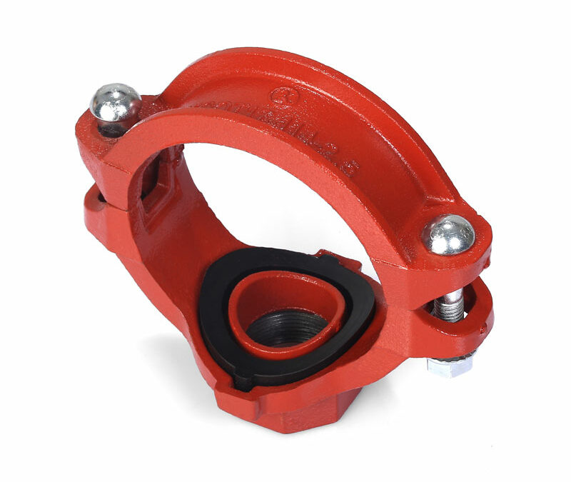
What is the difference between a mechanical joint and a grooved coupling? Both are mechanical methods for joining pipe, but they operate on different principles. A mechanical joint, typically used on ductile iron pipe with bells, uses a compression system where a gland and bolts compress a gasket into a socket. A grooved coupling, on the other hand, is used on pipes that have a groove rolled or cut into their ends. The coupling consists of two housing segments that engage with the grooves on the two pipe ends, a gasket that provides the seal, and bolts that hold the housings together. Grooved systems are extremely common in fire sprinkler systems and industrial applications.
Is special training required to learn how to install mechanical joint pipe and fittings? While a formal certification may not always be required, proper training is highly recommended. Understanding the principles of the joint, the importance of each step, and the correct use of tools like a torque wrench is essential for a reliable installation. Many manufacturers and industry associations offer training courses and field guides. Hands-on experience under the supervision of a seasoned installer is the best way to develop the necessary skills.
Why is lubrication so important for the gasket? Lubrication is essential for two reasons. First, it reduces the friction between the rubber gasket and the iron pipe surface. This allows the pipe to slide into the joint and past the gasket without dislodging, tearing, or twisting it. Second, it allows the gasket to move and adjust slightly as it is compressed, helping it to seat evenly and create a uniform, pressure-tight seal. Using the correct, approved lubricant is mandatory for a successful installation.
A Final Reflection on Craft and Connection
The process of joining two pipes, when examined closely, transcends mere manual labor. It becomes a demonstration of applied physics, materials science, and procedural discipline. The successful installation of a mechanical joint is a small but perfect union of human intention and mechanical function. It is a craft that requires not only the strength to move heavy materials but also the sensitivity to feel when a bolt is snug, the focus to follow a precise sequence, and the knowledge to understand why each step matters.
The integrity of our vast, hidden networks of pipes—the arteries and veins of our cities—depends on the quality of these individual connections. Each properly torqued bolt, each cleanly seated gasket, is a promise kept—a promise of reliability, safety, and longevity. To learn how to install mechanical joint pipe and fittings correctly is to become a steward of this promise, a participant in the vital work of building and maintaining the infrastructure that supports our world. It is a skill grounded in respect for the materials, an understanding of the forces at play, and a commitment to doing the job right, every single time.
References
American Water Works Association. (2017). AWWA Standard C111/A21.11-17: Rubber-gasket joints for ductile-iron pressure pipe and fittings. American Water Works Association.
American Water Works Association. (2022). AWWA Standard C600-22: Installation of ductile-iron water mains and their appurtenances. American Water Works Association.
Ductile Iron Pipe Research Association. (2023). The design of ductile iron pipe.
Jianzhi. (2024). Grooved fittings. Jianzhi Pipe Fittings. https://www.jianzhipipefitting.com/product/grooved-fittings/
Jianzhi. (2024). Grooved rigid coupling. Jianzhi Pipe Fittings.
Norton, J. P. (2021). Ductile-iron pipe and fittings (3rd ed.). American Water Works Association.
Moser, A. P., & Folkman, S. L. (2018). Buried pipe design (3rd ed.). McGraw-Hill Education.
Uni-Bell PVC Pipe Association. (2021). Handbook of PVC pipe design and installation (5th ed.).